
Using Pulse Per Second (PPS) Time Synchronization with External GPS on a Ladybug Camera
This application note describes how to configure the Ladybug camera's Pulse Per Second (PPS) feature to synchronize timestamps with an external GPS device that provides a PPS output.
Supported Products
Ladybug5+
Ladybug6
Overview
PPS is a common feature in GPS units and IMUs to provide an accurate timing signal to assist with precision synchronization of various devices to a common clock. It is commonly provided as a TTL signal at either 3.3 V or 5 V.
The Ladybug can directly accept PPS signals and NMEA data streams over the GPIO pins. This allows the Ladybug to maintain an internal precision time that is continuously synchronized with GPS time. Therefore, the timestamps attached to each image frame may be within microseconds of GPS time. The Ladybug does not process or output GPS positioning data.
The Ladybug cannot accept an RS232 signal from the GPS device. If your signal is RS232, you need to convert it to TTL for use with this feature.
Note: The Ladybug library can interface with a GPS device and insert NMEA sentence data into Ladybug images. The data can then be extracted later and be used to generate HTML data.
Test Configuration
| Item | Description |
|---|---|
| Camera | Ladybug6 |
| Firmware | 1.16.3.0 |
| Software | LadybugCapPro 1.20.0.79 |
Timestamp
The LadybugImageInfo contains the timestamp and shutter time information.
In trigger mode, the GPS timestamp is stored at the end of integration. The timestamp accuracy has a positive offset of 45 μs ±8 μs.
In free running mode, the GPS timestamp is stored at the start of integration.
To calculate the mid point of a frame's timestamp:
Mid Point = Timestamp - 45 μs - 0.5 x Shutter Time
Configuring the GPS Receiver
You can use a GPS receiver in conjunction with a Ladybug camera to record GPS data with stream files. Here we are using a EVK-F9P | u-blox as an example.
When using a GPS receiver with your Ladybug camera, please keep in mind:
- Your GPS receiver should have a serial or USB interface to connect to the host computer and be able to stream NMEA 0183 data in real time
- To provide reliable data, your GPS device should show a connection with at least 3 satellites
- It may take some time between when you first connect the GPS device to your PC and when it is recognized and configured for use with LadybugCapPro
- The following GPS NMEA data structures are supported: GPGGA, GPGSA, GPGSV, GPRMC, GPZDA, GPVTG and GPGLL
- LadybugCapPro is getting the GPS fix quality from the GGA sentence. This is required with either of the following:
- RMC: Recommended Minimum Navigation Information
- ZDA: outputs the UTC date and time
Detecting the GPS COM Port
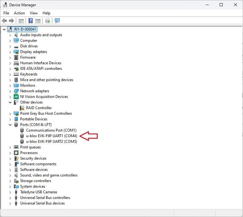
Using the GPS functionality requires the use of a GPS device. The COM port that the GPS device is connected to must be known. To determine the port, perform the following steps:
- Open Device Manager.
- Expand the "Ports (COM & LPT)" node and note the COM port that the GPS device is mapped to.
Configuring the GPS Baud Rate
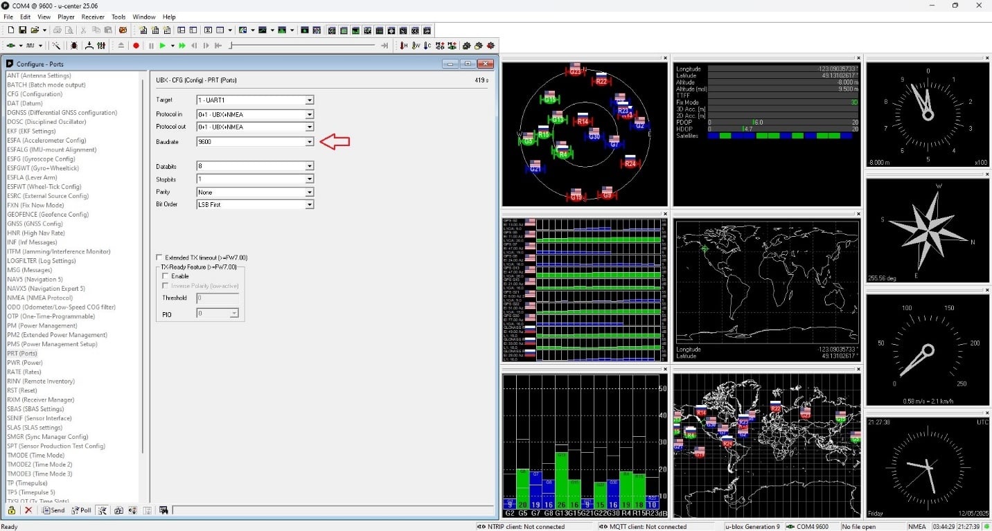
Once you know the COM port that you need to connect to, you should be able to connect to your GPS software and configure its Baud Rate. A Baud rate of 9600 is recommended.
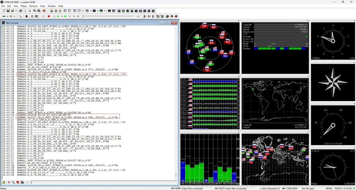
Configuring the GPS NMEA Data
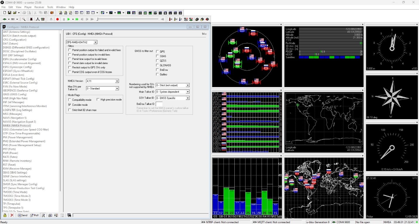
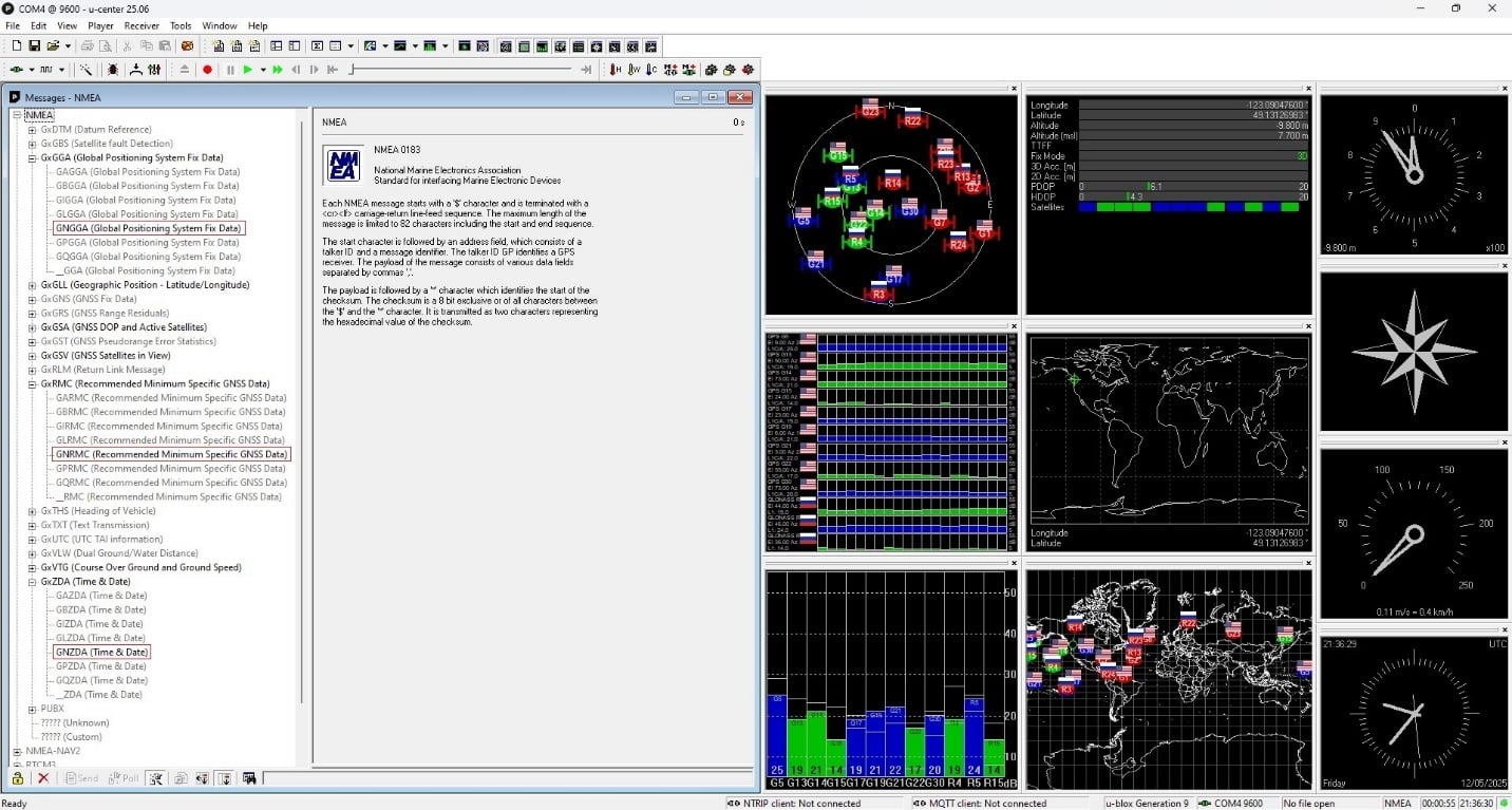
The NMEA sentences supported by the Ladybug library are:
- GPGGA
- GPGSA
- GPGSV
- GPRMC
- GPZDA
- GPVTG
- GPGLL
Please make sure you are sending GGA with RMC or ZDA as a minimum.
Configuring the PPS/Timepulse
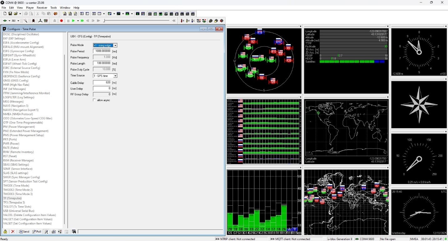
On the EVK-F9P, the TP (Timepulse) is enabled by default:
Connecting the GPS Receiver to the Ladybug Camera
Once you have configured your GPS receiver properly, you can connect it to the Ladybug camera for PPS time synchronization.
Ladybug Camera General Purpose Input/Output (GPIO)
The GPIO pin 4 (Orange, IO2) is used for GPS data.
The GPIO pin 11 (Yellow, IO3) is used for PPS signal, active on low to high transition.
The GPIO pin 12 (Black, GND) is used as a signal ground for IO2 and IO3.
The camera has a 12-pin GPIO connector on the bottom of the case; refer to the diagram below for wire color coding. The GPIO is a Hirose waterproof 12-pin female connector (Mfg P/N:LF10WBP-12SD).
| Diagram | Color | Pin | Function | Description |
|---|---|---|---|---|
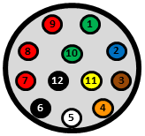 |
Green | 1 | OPTO_GND | Ground for opto-isolated IO pins |
| Blue | 2 | I0 | Opto-isolated input (default Trigger in) | |
| Brown | 3 | O1 | Opto-isolated output | |
| Orange | 4 | IO2 | Input/Output / GPS data | |
| White | 5 | +3.3 V | Power external circuitry up to 150 mA | |
| Black | 6 | GND | Ground for bi-directional IO, VEXT, +3.3 V pins | |
| Red | 7 | VEXT | Allows the camera to be powered externally | |
| Red | 8 | VEXT | Allows the camera to be powered externally | |
| Red | 9 | VEXT | Allows the camera to be powered externally | |
| Green | 10 | OPTO_GND | Ground for opto-isolated IO pins | |
| Yellow | 11 | IO3 | Input/Output / PPS signal | |
| Black | 12 | GND | Ground for bi-directional IO, VEXT, +3.3 V pins |
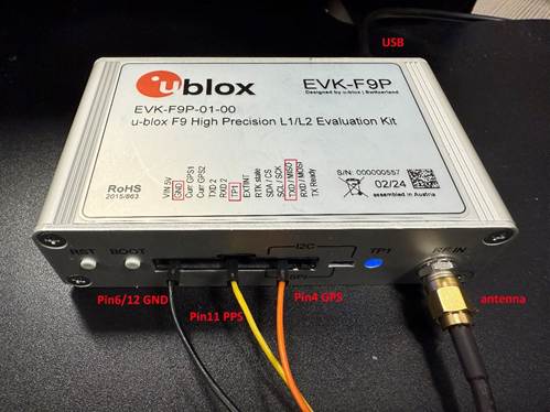
To achieve PPS synchronization, you need to make the following connections:
- Ladybug GPIO powered with an external 12 V DC power supply between Red (Pin 7/8/9, +12 V DC) and Black (Pin 6/12, GND)
- Ladybug USB3 to the host computer
- Ladybug GPIO Pin 4 (Orange, GPS data) to TxD
- Ladybug GPIO Pin 11 (Yellow, PPS) to TIMEPULSE 1 of the EVK-F9P
- Ladybug GPIO Pin 6/12 Black, GND to EVK-F9P GND
- EVK-F9P USB (or RS232) to host computer
- EVK-F9P antenna placed in a location with unobstructed view of the sky
Configuring GPS Time Synchronization
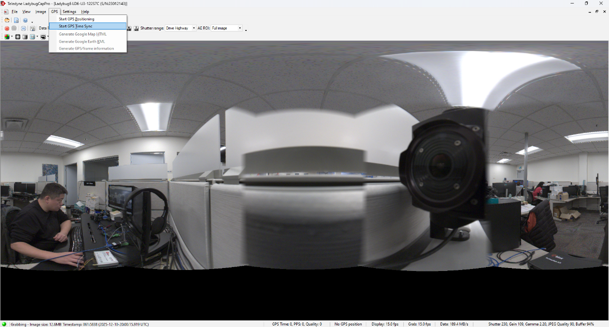
To start GPS time synchronization, launch LadybugCapPro and go to GPS-->Start GPS Time Sync:
Using the Ladybug API
There are two functions:
- ladybugSetGpsTimeSync()
- ladybugGetGpsTimeSync()
These take a camera context and a GpsTimeSyncSettings structure as follows:
- unsigned int baudRate
- bool enablePps
- bool enableGpsTimeSync
Using Camera Registers
| Offset | Name | Field | Bit | Description |
|---|---|---|---|---|
| 0x1EAC | PPS | Presence_Inq | [0] | Presence of the feature 0 = not available 1 = available |
| PPS_Inversion_Presence_Inq | [1] | Presence of the PPS Inversion Feature | ||
| [2-22] | Reserved | |||
| PPS_Inversion_Toggle | [23] | 0 = PPS low to high detect (default) 1 = PPS high to low detect |
||
| [24-30] | Reserved | |||
| PPS_Enable | [31] | Enable PPS 0 = disabled 1 = enabled |
| Offset | Name | Field | Bit | Description |
|---|---|---|---|---|
| 488h | SIO_CONTROL_CSR_INQ | SIO_Control_Quadlet_Offset | [0-31] | 32-bit offset of the SIO CSRs from the base address of initial register space |
| Base + 0h | SERIAL_MODE_REG | Baud_Rate | [0-7] | Baud rate setting 0 = 300 bps 1 = 600 bps 2 = 1200 bps 3 = 2400 bps 4 = 4800 bps 5 = 9600 bps (recommended) 6 = 19200 bps 7 = 38400 bps 8 = 57600 bps 9 = 115200 bps A = 230400 bps |
| Base + 4h | SERIAL_CONTROL_REG | RE | [0] | Enable receive Indicates if the camera's ability to receive data is enabled. Enabling this register causes the receive capability to be immediately started. Disabling this register flushes the the data in the buffer. 0 = disabled 1= enabled |
For a complete list of registers, see the Teledyne Machine Vision Camera Register Reference.
Verifying Time Synchronization Status
You can check the GPS Time, PPS, and Quality field in LadybugCapPro:
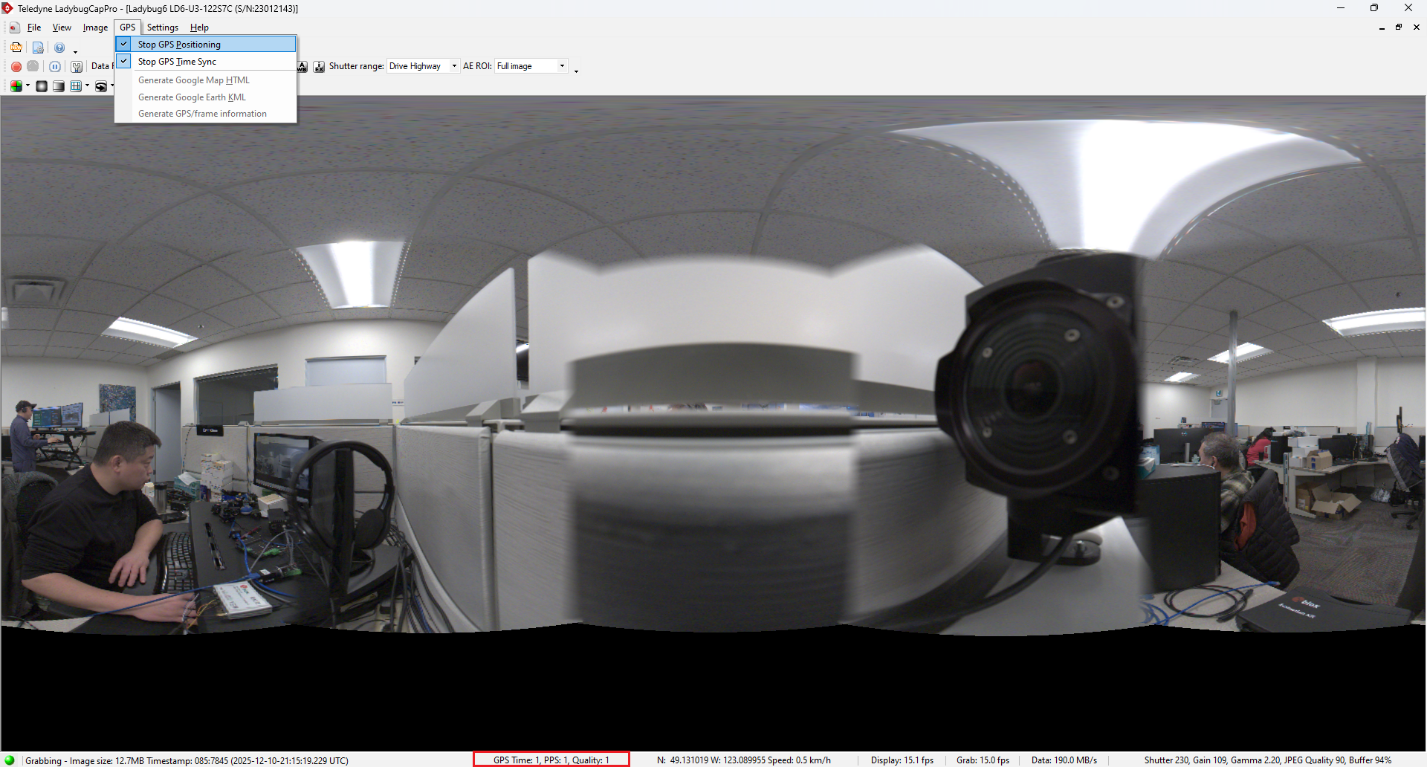
- GPS Time valid means the checksum is correct, and the sentence structure is correct.
For example, if GGA is valid, the checksum must be valid and parsed string must match
"GGA,%X,%X,%X,%X,%X,%U,%X,%X,%X,%X,%X,%X,%*"
Likewise, ZDA must have a valid checksum and look like "ZDA,%T,%U,%U,%U,%X,%*", and RMC must look like "RMC,%T,%X,%X,%X,%X,%X,%X,%X,%D,%*" - PPS is valid if interval is 1s +/- 500us, and jitter is less than 25us
- Quality: This is a number taken directly from the GGA fix quality field, refers to the reliability/accuracy indicator in NMEA GPS data.
| GPS | PPS | Quality | Comments |
| 0 | 0 | 0 | GPS time sync not enabled |
| 0 | 0 | X | PPS invalid, GGA valid |
| 0 | 0 | 15 | PPS invalid, GGA invalid |
| 0 | 1 | 0 | PPS valid |
| 0 | 1 | X | PPS valid, GGA valid |
| 0 | 1 | 15 | PPS valid, RMC or ZDA invalid, GGA invalid |
| 1 | 0 | 0 | PPS signal invalid, RMC or ZDA valid |
| 1 | 0 | X | PPS signal invalid, RMC or ZDA valid, GGA valid |
| 1 | 0 | 15 | PPS signal invalid, RMC or ZDA valid, GGA invalid |
| 1 | 1 | 0 | PPS signal valid, RMC or ZDA valid |
| 1 | 1 | X | PPS signal valid, RMC or ZDA valid, GGA valid |
| 1 | 1 | 15 | PPS signal valid, RMC or ZDA valid, GGA invalid |
X: a fix quality indicator number that is other than 0 or 15
Key GGA Fix Quality Indicators & Meanings
0: Invalid/No Fix.
1: GPS Fix (Standard Positioning Service - SPS).
2: DGPS (Differential GPS) Fix.
4: RTK Fixed (Real-Time Kinematic, highest accuracy, sub-centimeter).
5: RTK Float (RTK in convergence, meter-level accuracy) or Satellite-Based Augmentation (SBAS).
6: Dead Reckoning (estimated position).
9: WAAS (Wide Area Augmentation System).
If using the API, you can view the time synchronization status from the LadybugImageInfo:
- unsigned int ulGpsFixQuality
- bool bPpsStatus
- bool bGpsStatus
You can also verify the configuration using camera registers.
| Offset | Name | Field | Bit | Description |
|---|---|---|---|---|
| 0x1E9C | GPS_PPS_TIME_SYNC_VERIFICATION | Presence_Inq | [0] | Presence of the feature 0 = not available 1 = available |
| [1-23] | Reserved | |||
| GPS_Fix_Quality | [24-27] | Represents the quality setting from a GGA NMEA sentence | ||
| [28-29] | Reserved | |||
| GPS_Signal | [30] | GPS signal 0 = invalid 1 = valid |
||
| PPS_Signal | [31] | PPS signal 0 = invalid 1 = valid |
API Example
The API example ladybugGPSTimeSync demonstrates the configuration. The example is provided in the Ladybug SDK.