
Beyond Camera Specs: What Drives Line Scan Image Quality at Production Speeds
A practical guide to how resolution, line rate, exposure, lighting, synchronization, and system design affect line scan image quality.
Line scan imaging can feel counterintuitive at first. Many engineers are used to thinking about cameras in terms of two-dimensional sensors, yet some demanding inspection systems rely on a sensor that captures only one line of pixels at a time.
This is not a compromise. It is a different imaging approach for applications where motion, width, resolution, throughput, or available light dictate the system design. In high-speed production, line scan cameras can continuously inspect moving materials without stopping the process, supporting wide fields of view, and delivering high resolution across the entire width of a target. When motion is stable and synchronized with image acquisition, each line becomes part of a seamless, dimensionally consistent image. Achieving that image quality at production speeds depends on more than camera specifications. It depends on how the camera, motion system, optics, lighting, triggering, data path, and processing work together.
How Line Scan Builds a Two-Dimensional Image
In this context, a “web” refers to a continuous moving material such as film, paper, foil, fabric, glass, coated material, or similar production material. “Cross-web” refers to the width direction across the moving material, while “down-web” refers to the direction of travel.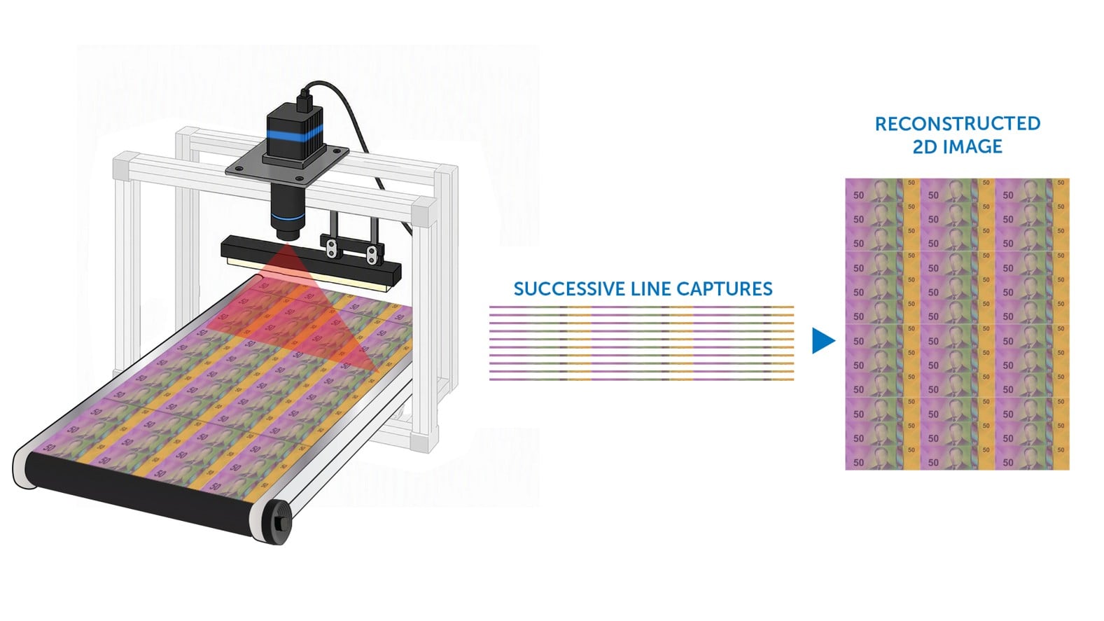
Figure 1. A line scan camera builds a 2D image by capturing successive lines as the target moves through the field of view.
A line scan sensor has a single row of pixels that spans the entire width of the target in the cross-web direction. Each exposure produces a one-dimensional array of pixel values. As the target moves past the sensor, successive lines are stacked over time to form a two-dimensional image. The second dimension is created by motion, rather than the sensor height, and the image length is determined by how long the system continues acquiring lines, unless terminated by artificial framing.
This is why synchronization matters so much in line scan imaging. If the camera acquires too many lines per unit distance, the reconstructed image is compressed in the direction of motion. If it acquires too few, it is stretched. These distortions are particularly problematic in metrology or defect classification, because geometric features change shape and algorithms lose their reference scale.
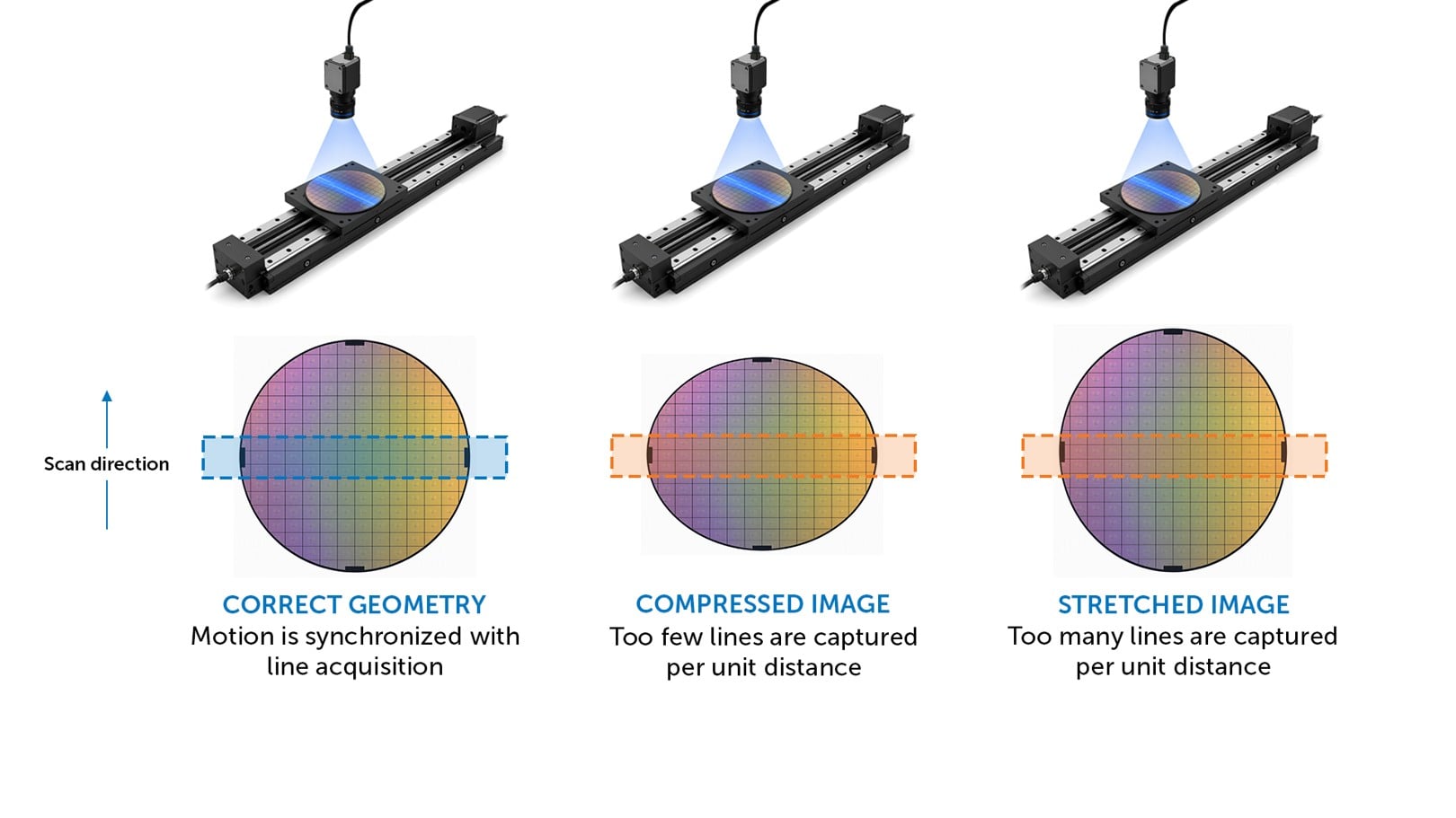
Figure 2. If motion and line acquisition are not synchronized, the reconstructed image can become compressed or stretched in the scan direction.
The most robust way to maintain dimensional accuracy is to trigger the camera from a motion encoder. Instead of running the camera at a fixed line rate and hoping the conveyor behaves, the system uses encoder pulses so that each line corresponds to a known increment of travel. Even minor speed variations can distort features, so encoders are commonly used to generate pulses for each increment of motion, often combined with scaling in motion controllers, cameras, or frame grabbers.
Driver One: Spatial Resolution in Both Directions
Line scan resolution has two independent components. Cross-web resolution is determined by the number of pixels in the sensor line and the optical magnification. Down-web resolution is defined by the travel distance represented by each acquired line, which is controlled by encoder scaling and the effective trigger frequency.
A practical starting point is to translate the inspection requirement into a pixel footprint of the object. If the web is 400 mm wide and the sensor has 16,384 pixels across the line, the nominal footprint is 400 mm divided by 16,384 pixels, which is roughly 24 micrometers per pixel before considering magnification or oversampling. If the smallest defect that must be detected is smaller than that footprint, you need either more pixels across the line, higher magnification, or both. Higher magnification reduces field of view, which can increase the number of cameras or inspection passes required.
Down-web sampling is equally important. If the target spatial resolution in the scan direction is 25 micrometers per line and the web moves at 2 m/s, the system must acquire 80,000 lines per second (2 m/s divided by 25 micrometers). If the web speed varies, encoder-based triggering preserves the 25 micrometers sampling by adjusting trigger timing to match the actual travel distance. This is the core advantage of distance-based triggering.
Driver Two: Line Rate, Exposure Time, and Signal Budget
Line rate is the number of lines acquired per second. It affects throughput, but it does not guarantee usable images on its own. Exposure time determines motion blur and signal level, and in high-speed inspection it often becomes the dominant trade-off. This is why camera selection should be based on the complete motion and lighting conditions, rather than only sensor format or speed specifications.
Short exposures reduce the photon budget. In light-starved applications, such as low-reflectance materials, coated films, or long working distances, signal must be recovered by increasing illumination intensity, choosing a sensor with higher quantum efficiency, increasing pixel size, reducing the f-number, or using Time Delay Integration (TDI).
TDI is a line scan technique that accumulates multiple exposures of the same moving object while synchronized with its motion, effectively increasing integration time without reducing web speed. In suitable applications, TDI can provide a substantial sensitivity advantages by accumulating multiple synchronized exposures, enabling higher inspection speeds in low-light conditions or reducing lighting levels at conventional speeds.
This is also where camera architecture becomes a strategic choice. A single-line CMOS camera can be ideal when illumination is sufficient, and system simplicity is a priority. A TDI camera is often the better choice when sensitivity limits throughput. Teledyne’s industrial line scan portfolio includes TDI cameras alongside single-line and multi-line options, allowing system designers to select the architecture that best matches the application’s illumination, sensitivity, and speed requirements.
Driver Three: Spectral Requirements and Contrast
After resolution, line rate, and exposure, the next question is whether specific spectral information is required. Many inspections do not require color. Instead, they rely on stable contrast, so monochrome cameras are used because they typically provide higher sensitivity (with no color filters) and often higher achievable line rates. They are well suited to applications such as scratch detection, crack detection, edge inspection, surface texture inspection, and code reading, where contrast is driven by intensity rather than color.
Color imaging becomes essential when the defect is defined by color variations, such as brand color verification, print inspection, textile sorting, or food grading. In line scan systems, color is commonly implemented with trilinear sensors that capture separate red, green, and blue lines. Those lines must be acquired so that the color channels align spatially, which adds calibration considerations. Color data can also help improve machine learning and AI-based inspection by providing additional spectral information that helps algorithms to distinguish normal process variations from true defects.
Some applications benefit from more than three bands. Multispectral and short-wave infrared line scan technologies can separate materials that look similar in visible light but differ spectrally, or they can increase defect detectability on reflective or coated surfaces by choosing a wavelength region with improved contrast. Teledyne’s line scan products include multispectral models, as well as UV and SWIR line scan models.
Driver Four: Optics, Lighting, Calibration, and Data Path
A line scan camera should be selected as part of a complete imaging system. The performance achieved depends on the lens, lighting, motion controller, trigger strategy, data interface, and computation pipeline.
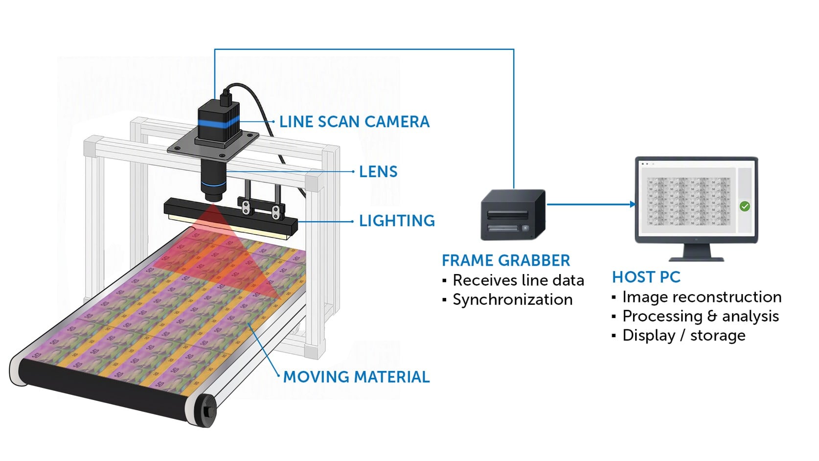
Figure 3. A line scan system depends on the full imaging chain, including camera, lens, lighting, synchronization, data acquisition, processing, and display or storage.
Optics are often the first hidden constraint. High-resolution line scan sensors can be physically long, requiring lenses with large image circles and careful control of distortion and aberrations across the full line.
Lens selection should consider modulation transfer function (MTF) at the spatial frequency of interest, relative illumination across the line, distortion, depth of field, and sensitivity to defocus caused by variations in web height. If the application includes measurement, distortion and telecentricity become more important. If the application is low contrast, MTF and flare control become more important.
Lighting is just as important. Line scan imaging concentrates on a narrow field of view, so illumination must be intense and uniform along the entire width. Flicker becomes a repeating artifact because it is imprinted line by line into the reconstructed image. For reflective targets, the illumination angle determines whether surface scatter or diffuse reflectance are emphasized. Polarization can be used to reduce glare, and diffusers can be used to reduce specular hotspots. The best lighting strategy is application specific and must be validated using the actual material.
Even with well-designed lighting, calibration is essential for low contrast inspection. Line scan cameras and frame grabbers support flat field correction so that residual illumination roll-off and pixel response non-uniformity do not appear as false defects. A robust calibration routine includes a dark reference to remove offsets, and a bright reference to normalize gain.
The final constraint is the data path. High resolution combined with high line rates produce very large data streams. If the interface cannot sustain the required throughput, the system may drop data or need to operate at a lower line rate. Teledyne Vision Solutions offers line scan cameras across interfaces including GigE, Camera Link (CL), Camera Link HS (CLHS), and CoaXPress (CXP), which provides flexibility for bandwidth, cable length, and electrical noise environments.
System Integration
Teledyne’s industrial line scan portfolio supports a wide range of inspection requirements, from compact, cost-optimized cameras and high-performance single-line models to multispectral, SWIR, TDI, and integrated contact image sensor solutions. The value of this portfolio is not simply product choice. It is the ability to select an imaging architecture that matches the real application constraints, whether that is illumination, installation space, alignment, scan width, bandwidth, or throughput.
A Final Practical Selection Sequence
A practical way to choose a line scan camera is to start with the inspection requirements and then validate the full imaging chain.
· Start with the inspection target - define the object width, the smallest feature or defect size, and the required pixel footprint across the line.
· Match motion to acquisition - define the maximum web speed, required down-web sampling, the effective line rate, and exposure time based on acceptable motion blur.
· Validate the system margin - confirm that the illumination, sensor architecture, optics, triggering, interface bandwidth, and processing latency can support the requirement at production speed.
At production speed, line scan image quality depends on the entire imaging chain, not on camera specifications alone.
Application Support
If you are evaluating a line scan system, Teledyne Vision Solutions can help translate inspection requirements into practical imaging architecture. Our application experts can help assess defect size, web width, web speed, motion profile, lighting, synchronization, interface bandwidth, and data path requirements, then match them to the right camera, optics, illumination, and integration approach.